


Shear Force in Slab and Beam
- Feb 11, 2018
- 3 min read
S.F in BEAM
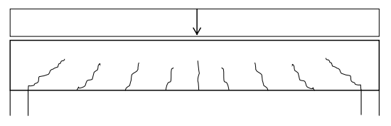
Reinforced concrete beams have a certain shear carrying capacity even when shear reinforcement is not provided. Shear reinforcement are also called stirrups or transverse reinforcement, and are usually placed in concrete members when the shear capacity of the concrete member without shear reinforcement is insufficient. The shear failure modes for beams without stirrups are shear sliding in the crack or crushing of the concrete. Both of them are brittle types of failures. The capacity against sliding is built up by different mechanisms interacting with each other. Friction within the inclined cracks is one of the contributing factors and depends partly on the size of the aggregates and partly on how much the crack has opened.
Consequently, the tensile flexural reinforcement also contributes to the shear capacity by holding the cracks together. In addition, the flexural reinforcement has a small resistance against deformations perpendicular to its direction. This is called dowel-action and is often considered less significant compared to the resistance from friction. It is also known that the shear capacity increases in concrete subjected to compression. Hence the compression zone in the top of the cross-section has a positive influence. Although these mechanisms are well known, the interactions between them are complex and the shear capacity of beams without transverse reinforcement is still a subject for research.
To avoid shear sliding in the crack, transverse reinforcement can be used. This increases the shear capacity significantly, since shear sliding now requires the stirrups to yield. The increased shear capacity will raise the risk of crushing of the concrete. This is because the concrete segments between the inclined cracks are subjected to compression in order to keep equilibrium, and the stress within them will increase for larger vertical loading. The risk of crushing in the concrete constitutes an upper limit for the shear capacity, whether stirrups are provided or not. The behavior of a reinforced concrete beam subjected to a distributed load can be explained with the truss model.
The dashed lines are called struts and represent compression. The solid lines are called ties and represent tension. When cracking has started in the concrete, the provided reinforcement will take the role of the ties. The horizontal tie in the bottom represents flexural reinforcement and the vertical ties represent stirrups.
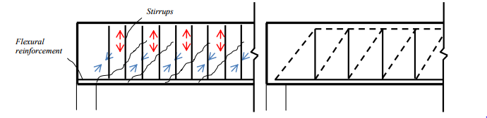
The behavior of a reinforced concrete beam and representation with a truss model. Vertical arrows and solid lines are tension. Inclined arrows and dashed lines are compression. When the load is close to the support, some part of it is directly transferred to the support by an inclined strut while some part needs to be carried up by the truss. The closer the load is to the support, the more of the load is carried directly by the inclined strut. Consequently, a smaller part of the load needs to be carried through friction or by the stirrups. This is a favorable effect that can be considered to make the design more effective.
S.F in SLAB
As slabs normally fall under the category of thin plates since the plate is used to carry out of plane loads and the span to thickness ratio is larger than 5,0. Thin plates are assumed not to have any shear deformations. In addition, an important cross-sectional moment is introduced in plates. It is called twisting or torsional moment (mxy) and must be taken into account in design of flexural reinforcement. Since the reinforcement bars do not always coincide with the principal direction of the bending moment, the presence of torsion will lead to an increased need of capacity in the reinforcement bars. In oppose to bending moment which has two principal directions orthogonal to each other, shear has only one principal direction. One can imagine observing a plate from above, realizing that the flexural reinforcement is aligned in two directions, while the transverse reinforcement is presented in points. Hence, it is possible to describe the maximum (principal) shear force with only a vector.
Often when designing concrete slabs, the designer wishes to avoid transverse reinforcement. This is especially true when designing bride decks where the loads are in motion and the use of stirrups in the entire slab is unpractical. A common measure to increase the shear capacity and avoid stirrups is to increase the thickness of the slab.
Comments